
High-speed turbines operate under extreme rotational forces, where even microscopic imbalances in rotor assemblies generate destructive vibration and excessive noise. These issues compromise bearing lifespan, reduce energy efficiency, and accelerate mechanical wear across critical drivetrain components. Understanding how a rotor balancing machine systematically eliminates these dynamic imbalances provides manufacturing engineers and maintenance professionals with a proven pathway to extend equipment operational life while achieving measurable reductions in vibration amplitude and acoustic emissions during sustained high-speed operation.
The fundamental relationship between rotor imbalance and turbine performance degradation stems from centrifugal force multiplication at elevated rotational speeds. When turbine shafts spin at thousands of revolutions per minute, even minor mass distribution asymmetries generate periodic forces that excite structural resonances and drive harmful vibration transmission throughout attached machinery. A rotor balancing machine addresses this challenge through precision measurement and corrective mass redistribution, enabling turbines to operate smoothly within acceptable vibration thresholds while maintaining acoustic performance standards critical for industrial compliance and workplace safety regulations.
The Mechanical Relationship Between Rotor Imbalance and Vibration Generation
Understanding Dynamic Imbalance in Rotating Assemblies
Dynamic imbalance occurs when a rotor's center of mass does not align perfectly with its rotational axis, creating an eccentric force vector that rotates with the shaft. In high-speed turbines, this imbalance manifests as two distinct phenomena: static imbalance where mass distribution is uneven in a single plane, and couple imbalance where unequal mass exists across multiple axial planes. A rotor balancing machine detects both conditions through precision vibration sensors and displacement transducers that measure the amplitude and phase angle of oscillation during test runs. The severity of vibration increases exponentially with rotational speed according to the centrifugal force equation, making balancing critically important for turbines operating above 10,000 revolutions per minute.
The physical mechanism driving vibration stems from Newton's second law applied to rotating systems. When an imbalanced rotor spins, the eccentric mass experiences continuous acceleration toward the rotation axis, generating a sinusoidal force that alternates direction twice per revolution. This periodic forcing function excites the natural frequencies of the turbine housing, shaft supports, and connected structures. Without intervention from a rotor balancing machine, these vibrations compound over operating hours, fatiguing metal components and loosening fasteners. The resulting mechanical degradation creates secondary vibration sources that further amplify noise levels and reduce system reliability.
Quantifying Vibration Severity and Acceptance Standards
International standards such as ISO 21940 establish precise vibration limits for rotating machinery based on rotational speed and application type. For high-speed turbines, acceptable residual imbalance typically ranges from 0.5 to 2.5 grams-millimeters per kilogram of rotor mass, depending on service conditions and performance requirements. A properly calibrated rotor balancing machine measures vibration displacement in micrometers or velocity in millimeters per second, comparing test results against these published thresholds. Engineers use these metrics to determine when corrective balancing becomes necessary and to verify that post-balancing vibration levels fall within operational specifications.
The relationship between imbalance magnitude and resulting vibration follows predictable patterns that rotor balancing machine software utilizes for correction calculations. Vibration amplitude is directly proportional to imbalance mass and its radial distance from the rotation axis, while being inversely related to system stiffness and damping characteristics. High-speed turbines with flexible shaft designs experience greater vibration sensitivity compared to rigid rotor configurations, requiring more stringent balancing tolerances. Modern rotor balancing machine systems incorporate these engineering principles into automated calculation routines that determine optimal correction mass placement for minimizing vibration across the entire operating speed range.
How Rotor Balancing Machines Measure and Correct Imbalance
Precision Measurement Through Vibration Analysis
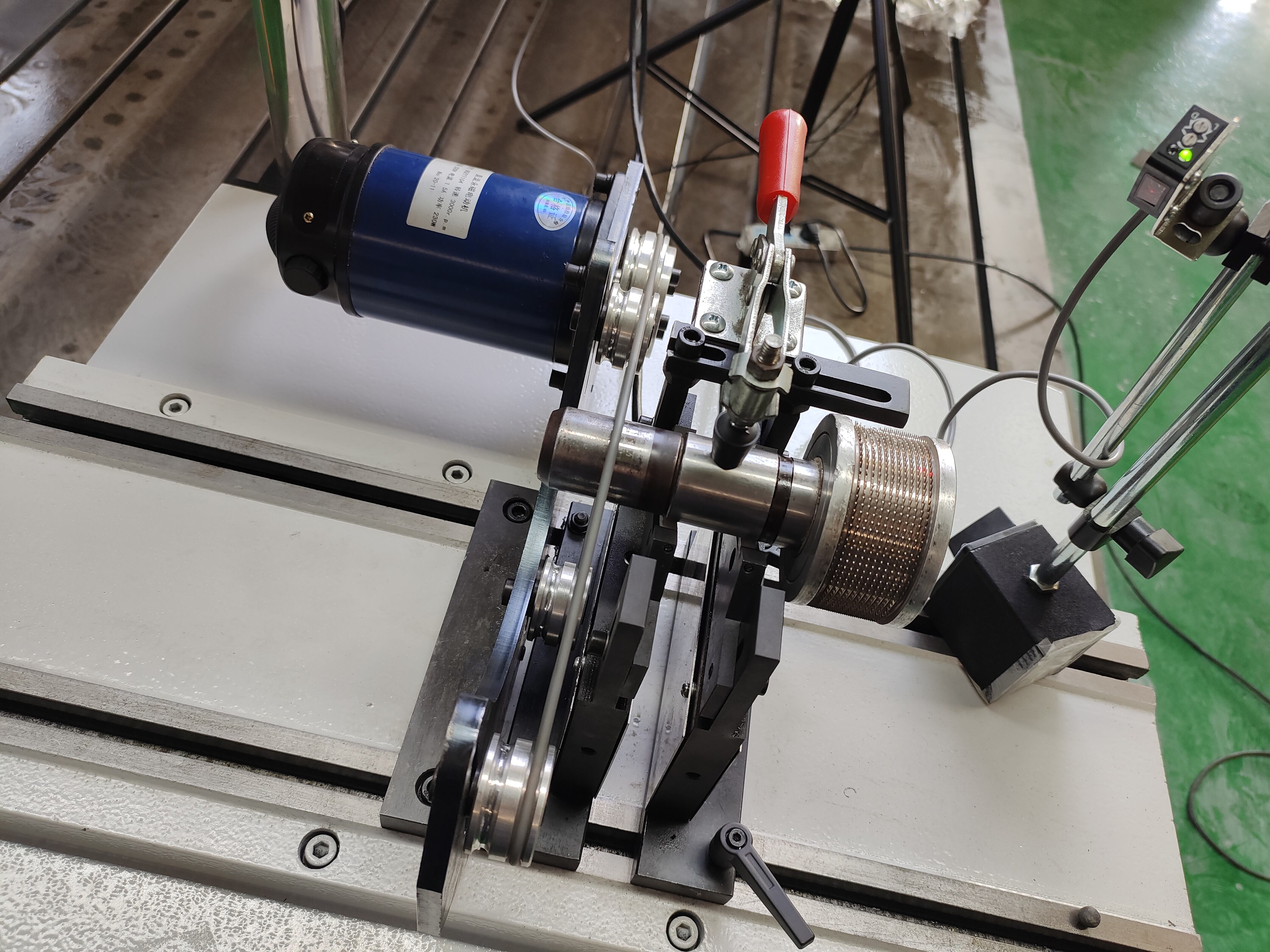
The operational sequence of a rotor balancing machine begins with mounting the turbine rotor assembly onto precision spindle supports equipped with low-friction bearings that minimize external interference during test runs. Piezoelectric accelerometers or laser displacement sensors attach to the bearing housings at strategic locations to capture vibration data in both horizontal and vertical planes. As the rotor balancing machine drives the assembly to specified test speeds, typically ranging from 500 to 15,000 revolutions per minute for turbine applications, the sensors continuously monitor vibration amplitude and phase angle relative to a fixed reference mark on the rotor.
Advanced rotor balancing machine systems employ frequency domain analysis to isolate vibration components caused specifically by imbalance from other sources such as shaft misalignment or bearing defects. Fast Fourier Transform algorithms decompose the raw vibration signal into constituent frequencies, with the fundamental frequency matching the rotational speed indicating pure imbalance. The phase angle measurement determines the angular location of the heavy spot on the rotor, while amplitude magnitude quantifies the severity of imbalance. This dual-parameter approach enables the rotor balancing machine to calculate both the mass and precise angular position for correction weights with accuracy exceeding 0.1 grams at specified radial distances.
Correction Weight Calculation and Placement Methodology
Once a rotor balancing machine completes initial vibration measurements, proprietary software applies influence coefficient methods to determine optimal correction strategies. The system calculates the exact mass and angular location needed to counteract the detected imbalance, accounting for the rotor's geometric configuration and material properties. For turbine rotors with accessible correction planes, technicians add or remove material through drilling, milling, or attachment of precisely weighed balance clips. The rotor balancing machine then performs verification runs to confirm that residual vibration meets specified tolerances, iterating the correction process if necessary until acceptable performance is achieved.
Modern rotor balancing machine designs incorporate multi-plane balancing capabilities essential for long turbine rotors exhibiting both static and dynamic imbalance components. Two-plane balancing addresses couple imbalance by placing correction masses at opposite ends of the rotor, while single-plane methods suffice for shorter assemblies where axial length is less than rotor diameter. The mathematical algorithms within rotor balancing machine control systems solve simultaneous equations representing the influence of trial weights on vibration at multiple sensor locations, determining the minimum correction mass distribution that satisfies vibration limits across all measurement planes simultaneously.
Vibration Reduction Mechanisms in Turbine Applications
Direct Force Cancellation Through Mass Redistribution
The primary mechanism by which a rotor balancing machine reduces turbine vibration involves creating an opposing centrifugal force that cancels the force generated by the original imbalance. When correction weights are positioned 180 degrees opposite the heavy spot at the same radial distance, the resulting force vectors sum to near-zero during rotation. For a turbine rotor spinning at 12,000 revolutions per minute, eliminating just 5 grams of imbalance at a 100-millimeter radius reduces periodic forcing by approximately 800 Newtons, dramatically decreasing transmitted vibration to supporting structures. This force cancellation principle remains effective across the entire operating speed range, provided the rotor behaves as a rigid body without significant elastic deformation.
The effectiveness of force cancellation achieved through rotor balancing machine procedures depends on accurately modeling the rotor's mass distribution and support conditions. Turbine rotors with complex geometries including blade arrays, coupling flanges, and shaft steps require sophisticated analysis to account for distributed mass effects. A high-precision rotor balancing machine captures these characteristics through multi-speed measurement protocols that identify how imbalance forces interact with structural flexibility at different rotational velocities. By optimizing correction weight placement based on comprehensive vibration mapping, engineers achieve vibration reductions exceeding 90 percent compared to unbalanced baseline conditions.
Minimizing Resonance Excitation at Critical Speeds
Every turbine rotor possesses natural frequencies determined by its mass, stiffness, and support boundary conditions. When operating speeds approach these critical frequencies, even small imbalances can excite large-amplitude resonant vibrations that threaten structural integrity. A rotor balancing machine plays a crucial role in minimizing excitation forces at these vulnerable speed ranges by reducing the fundamental forcing function amplitude. Precision balancing ensures that turbines can safely traverse critical speed zones during startup and shutdown without triggering damaging resonance conditions. For flexible rotor designs where critical speeds fall within the normal operating range, stringent balancing tolerances become essential for maintaining continuous operation.
The interaction between rotor imbalance and system resonance follows well-established mechanical principles that rotor balancing machine operators must understand for effective vibration control. Near critical speeds, vibration amplitude magnification factors can reach 10 to 20 times the static deflection, transforming minor imbalances into severe vibration events. By utilizing a rotor balancing machine to reduce residual imbalance below 10 percent of the allowable limit at operating speed, engineers create sufficient safety margin to prevent resonance amplification from causing operational disruptions. This preventive approach proves particularly valuable for turbines experiencing variable speed operation where multiple critical speeds may be encountered during normal duty cycles.
Noise Reduction Through Vibration Control
The Acoustic Transmission Path from Mechanical Vibration
Excessive turbine noise originates primarily from structure-borne vibration that radiates as airborne sound when mechanical oscillations reach surfaces capable of displacing surrounding air. When an imbalanced rotor generates periodic forces, these vibrations propagate through bearing housings, mounting pedestals, and connected piping systems, exciting large surface areas that function as acoustic radiators. The sound power level increases proportionally to vibration velocity squared, meaning that doubling vibration amplitude results in a six-decibel increase in radiated noise. A rotor balancing machine interrupts this transmission chain at its source by eliminating the fundamental forcing function that initiates the vibration cascade.
Frequency analysis reveals that imbalance-induced noise concentrates at the shaft rotational frequency and its harmonics, creating tonal components that dominate the acoustic signature of poorly balanced turbines. These pure tones prove particularly annoying to workers and easily exceed occupational noise exposure limits even when overall sound levels remain moderate. By employing a rotor balancing machine to reduce synchronous vibration components, facilities achieve targeted noise reductions in the specific frequency bands most problematic for hearing conservation and environmental compliance. Field measurements consistently demonstrate 8 to 15 decibel reductions in narrow-band noise levels following precision balancing of high-speed turbine rotors.
Secondary Noise Sources Eliminated Through Balancing
Beyond direct acoustic radiation from vibrating surfaces, rotor imbalance creates secondary noise mechanisms that compound the overall sound level. Excessive bearing loads caused by dynamic imbalance forces accelerate wear, generating elevated friction noise and impact sounds from increased clearances. Loose components rattling due to vibration excitation contribute broadband noise that masks communication and indicates impending mechanical failure. A rotor balancing machine addresses these issues indirectly by reducing the forcing functions that overload bearings and excite structural looseness. Maintenance records from industrial facilities show that implementing comprehensive balancing programs using precision rotor balancing machine equipment correlates with measurable reductions in both tonal and broadband noise components.
The cumulative acoustic benefit of rotor balancing machine application extends beyond the turbine itself to encompass connected auxiliary systems. Vibration transmitted through piping networks and drive couplings excites remote structures that become secondary noise radiators, expanding the affected acoustic zone. By minimizing source vibration through precise rotor balancing machine procedures, engineers reduce mechanical energy available for transmission throughout the facility. Acoustic surveys conducted before and after balancing interventions document noise reductions extending 50 meters or more from the turbine location, demonstrating the far-reaching impact of controlling vibration at its rotational source.
Operational Benefits and Performance Improvement
Extended Component Lifespan Through Reduced Fatigue Loading
The cyclic stress imposed by vibration constitutes a primary failure mechanism for turbine components operating under high rotational speeds. Bearing races, shaft journals, and fastener threads experience millions of stress reversals during typical service intervals, with vibration amplitude directly influencing fatigue life according to S-N curve relationships. A rotor balancing machine reduces peak cyclic stresses by minimizing dynamic loads, effectively extending component fatigue life by factors of three to ten depending on initial imbalance severity. Bearing manufacturers specify reduced load ratings for applications with excessive vibration, making precision balancing economically essential for achieving published life expectancies.
Quantitative reliability analysis demonstrates that turbines maintained within strict vibration limits through regular rotor balancing machine verification exhibit failure rates 40 to 60 percent lower than comparable units operating with marginal imbalance conditions. The economic value of this improvement includes reduced spare parts consumption, decreased emergency maintenance incidents, and extended intervals between planned overhauls. For high-value turbomachinery such as gas turbines and steam turbines used in power generation, the cost of rotor balancing machine services represents less than one percent of potential failure-related losses, establishing precision balancing as a high-return maintenance investment.
Energy Efficiency Gains from Reduced Parasitic Losses
Vibration consumes mechanical energy that would otherwise contribute to useful turbine output, creating measurable efficiency penalties in poorly balanced rotating equipment. The oscillating motion of an imbalanced rotor dissipates energy through bearing friction, structural damping, and aerodynamic drag effects associated with shaft whirling. A rotor balancing machine recovers this lost efficiency by minimizing unnecessary motion, with field measurements showing 0.5 to 2 percent efficiency improvements following precision balancing of large turbine rotors. For continuous-duty installations consuming megawatts of input power, these seemingly modest percentage gains translate to substantial annual energy cost savings that justify regular balancing maintenance.
The mechanism of energy loss reduction involves both mechanical and thermal pathways influenced by vibration amplitude. Excessive bearing loads caused by dynamic imbalance increase friction torque and heat generation, requiring enhanced lubrication flow rates and cooling capacity. Structural vibration dissipates energy through material hysteresis as components flex repeatedly under cyclic loading. By applying rotor balancing machine technology to minimize these parasitic losses, facilities reduce auxiliary system energy consumption while improving primary turbine efficiency. Comprehensive energy audits incorporating before-and-after power measurements validate the tangible efficiency benefits of maintaining turbines within stringent vibration specifications through systematic rotor balancing machine protocols.
FAQ
What vibration reduction can be expected after using a rotor balancing machine on a turbine?
Properly executed rotor balancing machine procedures typically achieve 85 to 95 percent reduction in synchronous vibration amplitude compared to pre-balancing levels. For high-speed turbines initially exhibiting vibration velocities of 10 to 15 millimeters per second, post-balancing measurements commonly fall below 1.5 millimeters per second, meeting ISO Grade G2.5 or better. The exact improvement depends on initial imbalance severity, rotor geometry, and the precision capabilities of the specific rotor balancing machine system employed. Turbines with rigid rotor characteristics and accessible correction planes generally achieve more complete vibration elimination than flexible rotors with limited balancing plane access.
How often should turbines undergo rotor balancing machine testing?
Maintenance schedules for rotor balancing machine verification depend on operating conditions, duty cycle severity, and vibration monitoring trends. Continuously operating turbines in critical service typically require annual balancing assessment, while intermittent-duty units may extend intervals to 18 or 24 months. Condition-based maintenance approaches use permanent vibration sensors to trigger rotor balancing machine intervention when measured levels exceed action thresholds, optimizing service timing based on actual need rather than fixed schedules. After major overhauls involving rotor disassembly or blade replacement, immediate balancing verification using a rotor balancing machine becomes mandatory before returning equipment to service.
Can rotor balancing machines address noise issues in existing turbine installations?
Yes, rotor balancing machine application provides effective noise reduction for turbines exhibiting imbalance-related acoustic problems, even in mature installations operating for years. The process requires removing the rotor from service, transporting it to a facility equipped with appropriate capacity rotor balancing machine equipment, and performing precision balancing to current standards. Field experience shows that retrofitting older turbines with modern balancing tolerances delivers 8 to 12 decibel noise reductions in tonal components at rotational frequency. This approach proves particularly cost-effective compared to acoustic enclosure construction or wholesale equipment replacement when addressing noise compliance issues.
What distinguishes high-precision rotor balancing machines for turbine applications?
Turbine-grade rotor balancing machine systems feature enhanced measurement resolution, extended speed range capability, and sophisticated multi-plane balancing algorithms essential for complex rotor geometries. Key differentiating characteristics include vibration measurement sensitivity below 0.1 micrometers displacement, speed capacity exceeding 12,000 revolutions per minute, and software capable of resolving correction requirements for rotors with length-to-diameter ratios greater than three. Advanced rotor balancing machine designs incorporate motorized spindle drives, automatic weight calculation, and permanent calibration verification to ensure consistent accuracy meeting ISO 21940-11 standards for balancing machine performance verification.
Table of Contents
- The Mechanical Relationship Between Rotor Imbalance and Vibration Generation
- How Rotor Balancing Machines Measure and Correct Imbalance
- Vibration Reduction Mechanisms in Turbine Applications
- Noise Reduction Through Vibration Control
- Operational Benefits and Performance Improvement
-
FAQ
- What vibration reduction can be expected after using a rotor balancing machine on a turbine?
- How often should turbines undergo rotor balancing machine testing?
- Can rotor balancing machines address noise issues in existing turbine installations?
- What distinguishes high-precision rotor balancing machines for turbine applications?

